Wanted: The Perfect Impedance
Posted 05/01/2019 by Bird RF Engineer
Since 1942, Bird has been supplying quality instruments for RF power measurement for 50 ohm coaxial line systems, and since 1942 we have had customers asking why 50 ohms is the standard impedance in the United States. This is a great question! So today, we will explore why 50 ohms has become the integer-of-choice in the US as well as the math behind this decision.
In concentric transmission lines, the electromagnetic wave is propagated through a dielectric medium bounded by two coaxial cylinders. Since current penetration at microwave frequencies is small (skin depth at 1 GHz in a silver conductor is approximately 0.00008 inches), the only important dimensions are the diameter (d) of the center conductor and the bore (D) of the outer conductor.
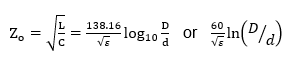
For a coaxial line with small losses, such as used in the industry, the characteristic impedance (see equation below) is where L and C are the inductance and capacitance per unit length and ε is the dielectric constant of the medium between the concentric cylinders (ε equals 1 for air).
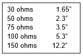
For example, here are a few representative outer-conductor bore values for an airline with a one-inch diameter center conductor:
There is no diameter ratio that is ideal for all important transmission parameters. In a coaxial line with power propagating in normal TEM mode, the highest voltage gradient occurs at the surface of the center conductor. Using a maximum Breakdown Gradient Em (e.g. 74 peak volts per mil for air), the highest permissible potential difference between conductors is then
This leads to the curve of Breakdown Voltage in Fig. 1. The curve peaks at a diameter ratio of 2.718 which corresponds to a 60-ohm impedance.1
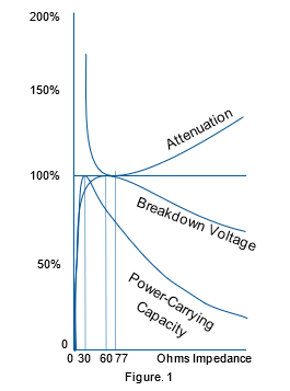
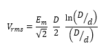
Power, of course, is V2rms/Zo. The curve of Power Carrying Capacity in Fig. 1 is a plot of
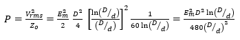
If, for example, Vmax of a 60-ohm line is assumed to be 100Vrms, the maximum power associated with this Vmax would be 167 watts. A 30-ohm line with the same outer conductor diameter can only sustain a Vmax of 82.5Vrms before breakdown. The power associated with this Vmax , however, is 82.52/30 or 226 watts, i.e. the 30-ohm airline has a higher Power Carrying Capacity, but a lower Breakdown Voltage than the 60-ohm line.
Power capacity based on voltage considerations ignores the current density, which goes up as impedance goes down. Attenuation due to the conductor losses alone is almost 50% higher at 30 ohms than at the minimum-attenuation line-impedance of 77 ohms (Diameter ratio of 3.6). Since such a line is limited to only about half the power capacity of a 30-ohm line, 77 ohms is usually selected for low-power long-distance transmission (e.g. CATV, TV antenna lead-in, etc.). According to Consultant C.L. Rouault, an RMA committee in the 40’s recommended an impedance standard of 50 ohms to the U.S. Navy as a compromise between transmission parameters, as well as commercially available copper water-tubing sizes. It is interesting to think where the communication industry might be today without input from the plumbers!
Adding Attenuators
While minimum attenuation is desirable in signal transmission, equipment with a known amount of attenuation is a valuable tool in the laboratory.
Coaxial attenuators are used for a variety of applications such as isolation, comparison standards, power reduction at the source or at the receiving end, and for signal observation. Components under test, such as filters and antennas, typically exhibit impedances other than 50 ohms. In these cases, fixed attenuator pads are used to reduce interaction between components in order to make measurements meaningful.
For example, a matched 10 dB pad reduces a 2:1 voltage standing wave ratio to 1.07, a 3:1 VSWR to 1.11, and so on. Figure 2. demonstrates the correlation between the three parameters of dB attenuation and VSWR before and after attenuation. Since this is accomplished at the expense of power level, Figure 2. shows the best compromise between correlating the three parameters of dB attenuation and VSWR before and after attenuation.
Points on the graph have been calculated from the following relationships:
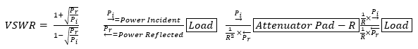
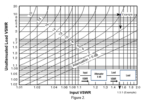
When a pad is added, the power level into the attenuator (Pi) remains unchanged and is then reduced by the attenuator’s ratio (10:1 for 10 dB, 100:1 for 20 dB) to 1/R×Pi. This reflected level passes through the attenuator and is reduced again by the attenuation ratio (1/R x 1/R x Pr). The new VSWR is then

The values for each point have been calculated to five significant places and plotted in Figure 2.
Attenuators are also used for signal observation, such as scope display or counters. They reduce the line signal level to an amount the test equipment can utilize without distortion. Attenuators for these applications and for power measurement with low level wattmeters must be designed to withstand the higher power dissipated within their elements.
Whether you’re measuring the “gold standard”, 50 ohm coaxial line, or working in the lab testing other impedances, Bird manufactures a broad spectrum of quality instruments including attenuators from 2W to 4000W. Our resistive product portfolio includes air-cooled, water-cooled, oil-dielectric, convection cooled, and conduction cooled RF attenuators with a wide range of connectors and attenuation values. For more information on these products and more, visit us at BirdRF.com.