RF Termaline Loads
Posted 07/09/2019 by Bird RF Engineer
We make loads of loads! From low-level laboratory loads to high-power loads, air-cooled and water-cooled loads, pulse loads and continuous signal loads, we make them all. So, it’s safe to say we’ve got the low-down on loads!
Most users think of a load as a resistor at the end of a line and that is that. As the self-described load expert, I’m here to tell you there is far more to loads than meets the eye, so let’s take a deeper look at the humble load and explore this invaluable component.
The Load: A Brief History
To truly understand the load, one must understand how the load came to be. Let’s start by looking at the RF energy transmission line in Fig. 1. A line for the transmission of RF energy may be represented by an infinite number of incremental series inductances, each shunted by a capacitor. The values of these incremental reactances depend on the physical structure of the line, but any one construction possesses a characteristic impedance which is given by Z0=√(L/) √C and, for a loss-less line, is purely resistive.
If the line is air-filled it consists of a conductor centered in a hollow tube with a diameter ratio of 2.3, and has 4.2 nanohenries series inductance and 1.69 picofarads shunt capacity per inch.
As long as the RF wave travelling along this line sees nothing but 50 ohms, it will propagate without reflections. This can be assured in many ways; The simplest way, and possibly the earliest, was to continue the line ad infinitum (or nearly so). Since cables are never loss-less, an engineer looking to do maintenance or adjustments on a transmitter while “off-air” would connect a large coil of cable in place of the antenna and hope that most of the energy would be dissipated in the cable losses before it reached the open end of the coil. While this method served its purpose, later on someone improved this technique by making the center conductor of the long cable coil resistive, thus cutting infinity to size!
Since an infinite line looks like resistance, the obvious progression was to replace it with a resistor. The only problem was that no resistor available at the time looked like an infinite line, or in other words like pure resistance.
Solid rod resistors change value as the RF frequency is increased because the current concentrates on the surface. To combat this, the industry soon developed film resistors with coatings 1/100 and even less than 1/1000 the skin penetration of the RF current. The “only” remaining problem was to mount the resistor at the end of the line without any undesirable reactances. Fortunately, the patent records held plenty of solutions to this problem.
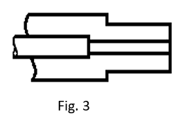
First, a resistor was mounted on the end of the center conductor and the line abruptly terminated (Fig. 2). This worked for low frequencies and when the line dimensions around the resistor were chosen as R/√3 (e.g. 50/√3= 29 ohms), the arrangement was useful to a minimum wavelength 15x the resistor length. In other words, a 12” long resisitor would be fair to about 65 MHz. A higher frequency would quickly raise the impedance and become capacitive. If the dimensions were R/√5 (e.g. 50/√5= 22 ohms), the real part of the impedance would remain at 50 ohms for frequencies about 2.5 times higher than before, but a capacitive reactance would appear from the start. This was corrected by a short series inductance (Fig. 3) and the 12” resistor was now usable to 160 MHz.
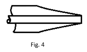
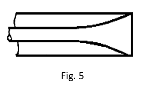
By now it was clear that in order to build a frequency-independent matched termination, the shell of the resistor should be matched to it at any point along its length. This led to the development of Figs. 4 and 5. Here the line has an impedance of 50 ohms at the start of the resistor, 25 ohms at the half way point and 0 ohms at the end. The diameter ratios are calculated according to er/60, where r is the resistance remaining between any cross section and the end of the resistor. The shape of an outer conductor for a cylindrical center resistor (Fig. 4) is exponential. To this day, this is how we build nearly all of our loads, wattmeters, and attenuators! (Fig. 5 is a theoretical, though not very practical, corollary where an exponential inner conductor is surrounded by an outer resistor.)
At centimeter frequencies (3 GHz and up), solid dissipative material offers some advantages for higher power ratings. Before absorbent microwave materials were available, such as are now used in tapered constructions3 shown in Fig. 7 and 8, experimenters mixed their own. We included a recipe for Aquadag-coated sand at the end of this post (just in case you’re looking to experiment on your own!) which was used in the first high-power 10 cm load4.
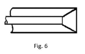
An interesting and nearly ideal arrangement for lower power loads is the cone resistor (shown in Fig. 6) and the disc resistor, which is really a cone with its included angle increased to 180°. However, the major draw-back of such terminations is the unequal distribution of power dissipation. Most of the heat is generated near the center conductor, where the surface area is small and heat conduction difficult5.
The Modern Load
There are many variations on these basic schemes, however we prefer a refined version of Fig. 4. The exponential outer shell is a close approximation to theory, especially when the resistor is much longer than the outer conductor diameter. With a short resistor, the curvature of the radial electric field lines, which are perpendicular to the shell surface and nearly perpendicular to the resistive film, can’t be ignored any longer. The proper profile of the shell is a curve to which the length of the tangent to the axis is a constant, in other words a tractrix.
Though they go by many names, including “termination resistors” and “dummies”, loads may appear simple but have a complex legacy in our industry! Be sure to check out our legacy of loads and shoot us an email or give us a call with any questions.